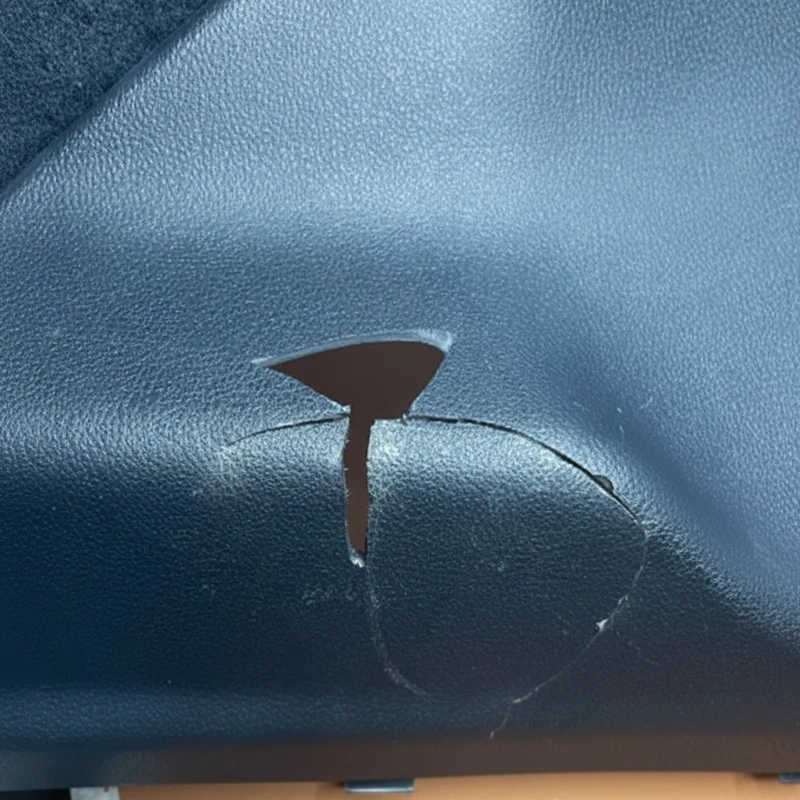
Last month, we handled a typical case: a client’s automotive interior parts were frequently cracking under low winter temperatures (-15℃), with a return rate as high as 15%. Upon disassembly, we found they used standard PP rather than impact-modified PP. The material itself lacked sufficient low-temperature impact strength, and the mold did not compensate for PP’s high shrinkage, leading to stress concentration and cracking during assembly.
This is not an isolated case—we encounter numerous injection molded defects (sink marks, weld lines, dimensional deviations), and almost all trace back to two core issues: wrong material selection and mold design not matched to material properties. For example, a client once misused ABS as PP, resulting in a 40% drop in part strength— a classic chain reaction caused by “material and mold mismatch”.
Step 1: Choose the Right Material
If the material is wrong, even the most precise process is futile. We’ve seen clients use ABS for high-temperature parts (which actually require PA66) and ordinary PE for medical-grade products (which should use medical-grade PE). The result is either underperformance or doubled costs.
Why Material Selection is Critical
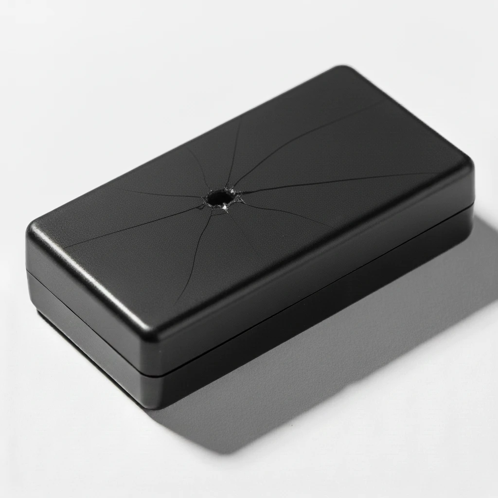
Core parameters such as plastic shrinkage, flowability, temperature resistance, and mechanical properties directly determine whether a product meets its usage requirements. For example, PP has good flow but high shrinkage (1.5–2.5%), and ABS has high strength but poor flow. Wrong material selection can lead to:
- Performance failure (e.g., low-temperature cracking, high-temperature deformation)
- Process difficulties (incomplete filling, trapped air burn marks)
- Cost waste (high material price used in wrong scenarios)
Five-Step Material Selection Template
We always follow this internal logic to help clients mitigate risks from the start:
- Define requirements: List product core indicators (temperature range, load requirements, environmental media, appearance grade)
- Candidate material screening: Match materials from the material library based on requirements (e.g., medical-grade: ABS/PC; high-temperature: PA66/PPS)
- Performance testing: Test key indicators (impact strength, heat distortion temperature, high/low temperature cycling if necessary)
- Prototype validation: 3D print or small-batch trial production to simulate actual usage scenarios
- Cost optimization: Prioritize more cost-effective materials while meeting performance requirements (e.g., use HIPS instead of ABS for non-load-bearing housings)
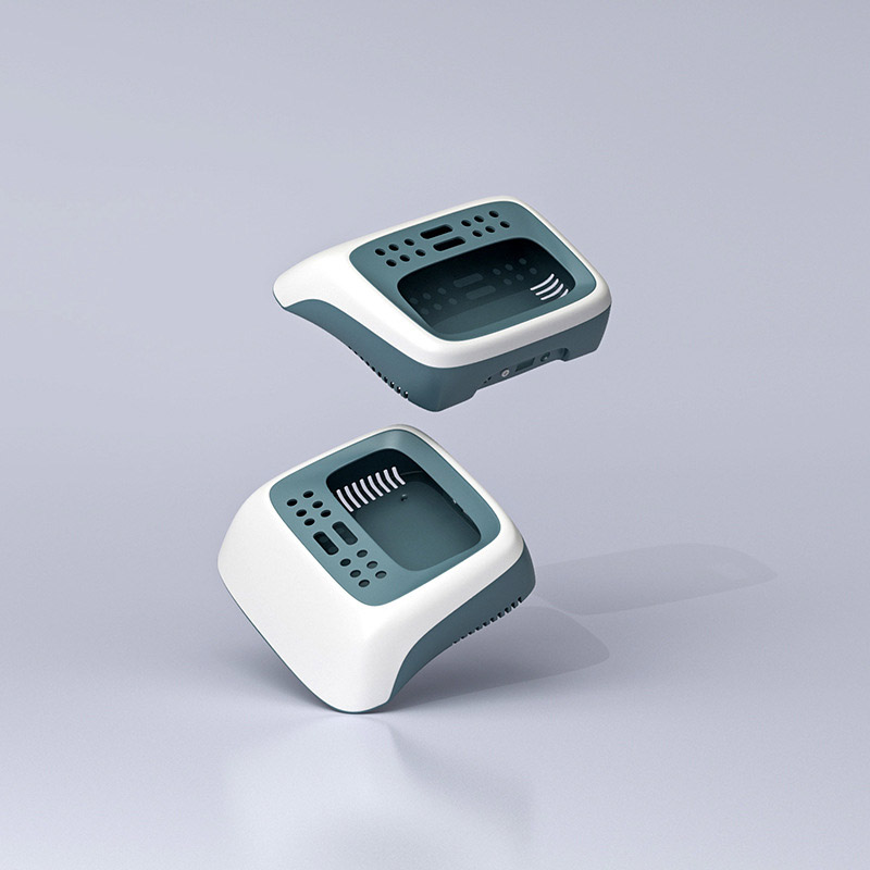
Step 2: Design the Mold According to Material Characteristics
After selecting the right material, the mold must “follow the material. Different materials have significant differences in shrinkage, flowability, and crystallization characteristics. Using the same mold parameters for PP and ABS will inevitably result in severe sink marks for one and dimensional deviations for the other.
Key Adjustment Points (with Specific Parameters)
1. Shrinkage Compensation: Calculate Cavity Dimensions Accurately
Plastics shrink after cooling, so mold cavity dimensions must be enlarged according to: cavity dimension = part dimension × (1 + shrinkage rate). Crystalline plastics (e.g., PP, PE) exhibit high shrinkage and are strongly influenced by mold temperature (higher mold temperature increases crystallinity and shrinkage). In contrast, amorphous plastics (e.g., ABS, PC) exhibit lower, more stable shrinkage.
- PP: Shrinkage 1.5–2.5%, cavity enlarged by 1.8% (median value), mold temperature controlled at 50–70℃ to reduce shrinkage fluctuation
- ABS: Shrinkage 0.5–0.8%, cavity enlarged by 0.6%, mold temperature 60–80℃ to improve surface gloss
2. Gate Design: Match Material Flowability
High-flow materials (PP, PE) can use smaller gates (e.g., pin gate diameter 3mm). Low-flow materials (ABS, PC) require larger gates (e.g., a fan-shaped gate with a width of 8mm); otherwise, incomplete filling or excessive pressure loss occurs. For example, PP gates can be small, but they must include packing and shrinkage compensation to avoid sink marks. ABS requires large and multiple gates to balance filling and reduce weld lines.
3. Cooling System: Control Crystallization and Internal Stress
- Crystalline plastics (PP): Require uniform cooling to prevent uneven shrinkage from local temperature differences (recommended cooling channel spacing ≤50mm)
- Amorphous plastics (ABS): Require rapid cooling to fix the shape and prevent warping (cooling channels close to cavity surface, distance 15–20mm)
4. Mold Material Selection: Adjust According to Material Abrasiveness/Corrosiveness
- Glass fiber reinforced materials (e.g., PA66+30% glass fiber) wear the cavity; use S136 hardened steel (HRC ≥50)
- Standard PP/ABS: 718H pre-hardened steel (HRC 30–35) balances cost and mold life
Example for ABS:
- Material side: Select high-flow ABS (e.g., PA-757) to improve filling
- Mold side: Add vent slots (depth 0.03mm, width 5mm) to address weld lines; position gates away from visible surfaces
Conclusion
There is no shortcut to producing high-quality injection molded parts: first, precisely select the material, then customize the mold according to the material’s characteristics. The material determines “whether it can be made,” and the mold determines “how well it can be made.” Combining both can prevent 90% of common defects from the source.
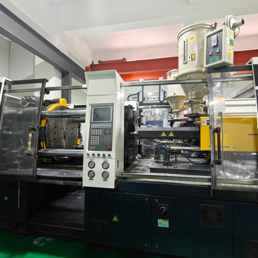
The Worldboundgroup Plastic Products team has handled over 3,000 mold sets. Our deepest insight is: injection molding is not just “processing according to the drawing,” but a “co-engineering of material and mold.”