You are updating an existing product: making the housing thinner and moving a button while keeping the functions and main components. If only the appearance is changing, why does the internal mechanical design need another review?
The housing also supports components, transmits button force, and joins the upper and lower covers. Changing its outer shape can change these positions and interfaces. From Worldboundgroup’s perspective in product development, tooling, and injection molding, evaluating a redesign means checking whether the parts will still fit together and whether the buttons and connections will still work.
A button, a snap fit, and a screw are enough to show how these relationships work.
If You Move the Button, What Presses the Switch Inside?
The plastic button you touch and the switch that actually sends the signal on the circuit board are often separate parts. Consider a design in which a plunger behind the button directly presses the switch. Your finger pushes down, the plunger transmits force to the switch, and the product receives a command when the switch operates.
If you move the button sideways to improve the appearance but leave the switch in its original position on the circuit board, the plunger may no longer line up. You may need to change the structure behind the button or move the switch. Moving an opening in the housing alone does not mean everything inside will still work as before.
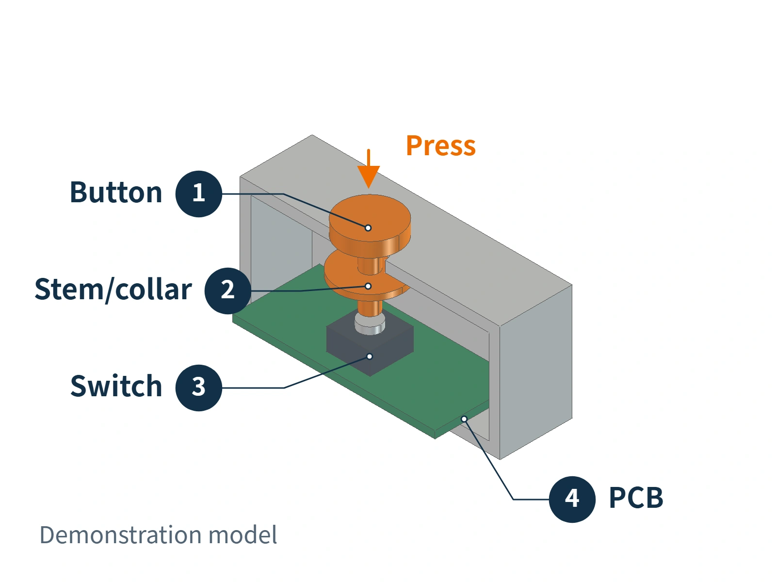
Now consider another change: lowering a raised button to make the surface flatter. If you lower only the exposed top while keeping the plunger, its clearance to the switch, and the available travel unchanged, the internal fit may not need adjustment.
But if you also shorten the plunger or change the point at which the button stops against the housing, you need to check whether it can still press the switch and how far it moves before stopping. The button might hit the housing before the switch actuates. Alternatively, it might continue transmitting excessive force to the switch and circuit board after actuation.
Here, “travel” means the distance the button moves when pressed, and a “stop” is the feature that prevents further movement at a set position. Insufficient travel may prevent actuation; travel beyond the permitted range may damage the switch. Omron’s switch usage guidance emphasizes operating direction and travel settings. Public application guidance from Alps Alpine also connects housing stops with preventing excessive loads on switches and circuit boards.
Changing a button’s appearance therefore requires checking its internal alignment, travel, and stop position together. The outside should look right, while the mechanism inside must stay aligned, reach the switch, and stop where it should.
Why Isn’t a Thicker Snap Fit Necessarily More Durable?
A snap fit on a plastic housing may look like a small projection with a hook. In a cantilever snap fit, the root connects to the housing, the projecting beam acts as a flexible arm, and the hook sits at its tip. During assembly, the arm must bend so that the hook can pass a ledge on the other housing half. It then returns to position and holds the two parts together.
In other words, the snap fit must resist separation once engaged while still allowing enough deflection during assembly.
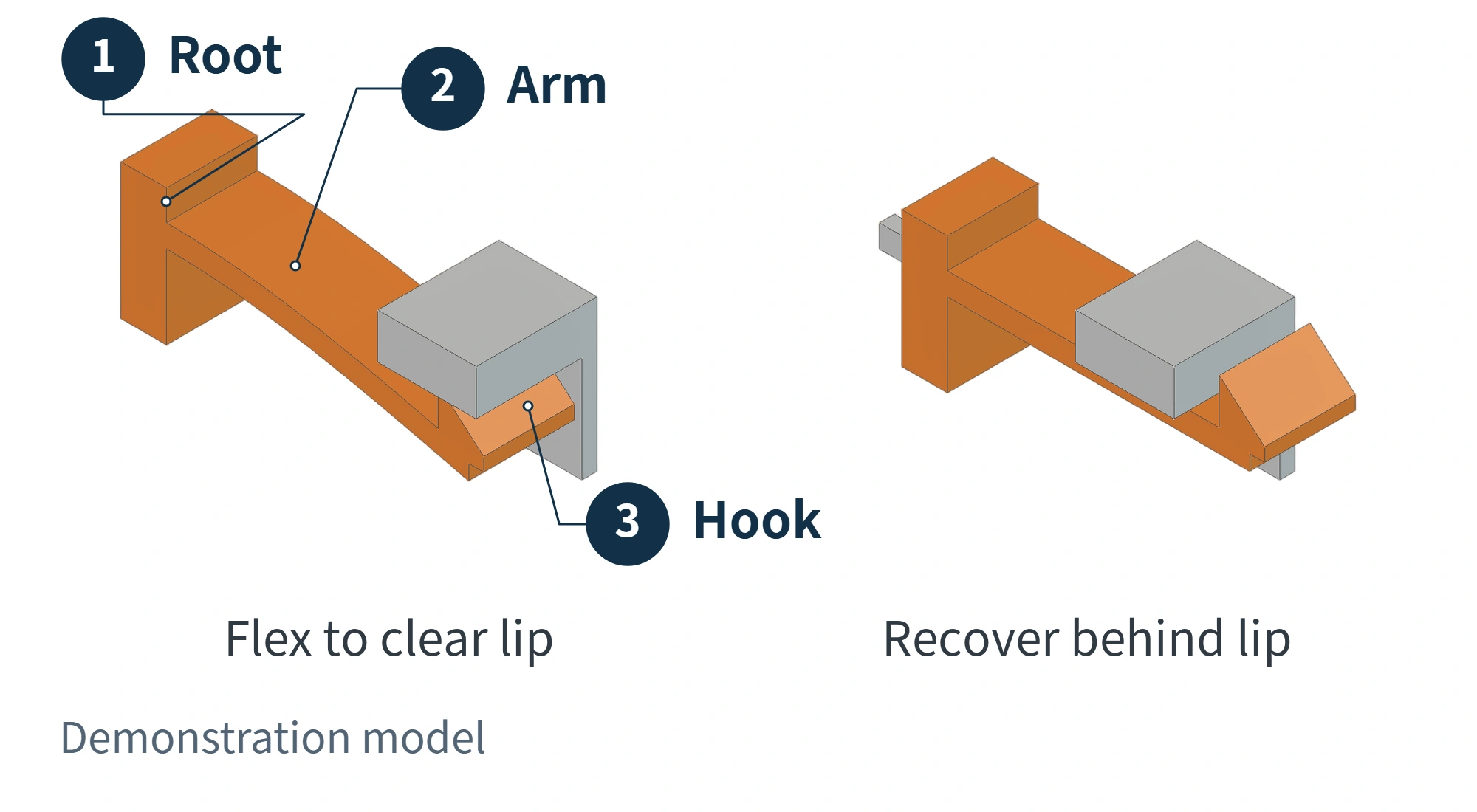
Suppose a more compact housing leaves less length for the snap-fit arm, but the arm still has to deflect by the same amount during insertion. Its bending conditions have changed. Making it thicker does not automatically make it more reliable: it may become harder to bend, so both the assembly force and the deformation at the root need to be reassessed. Whether the material can accommodate that deformation also affects the outcome.
Covestro’s snap-fit design guidance considers length, cross-sectional shape, and required deflection together. BASF’s technical discussion further notes that the housing wall supporting the snap fit can also deform. Looking only at the hook and asking whether it is thick enough misses part of the problem.
There is another tradeoff at the root. When the snap-fit arm bends, tensile or compressive loading can concentrate in a small area there, creating a weak point. A smooth transition between the arm and housing can reduce this stress concentration. However, making the fillet progressively larger can create an overly thick section at the junction. After molding, this may cause a local surface depression, known as a sink mark, or an internal void. That is why even a small snap fit may need repeated changes to its shape.
A snap fit must both go together and stay together, and its geometry must also allow consistent molding. Once the housing profile changes, the original snap fit may no longer work unchanged.
Why Can Hiding a Screw Mean Changing the Boss Inside?
For a cleaner appearance, you might move a screw from the front to the back or hide it in a recess. But the screw position usually needs a corresponding fastening feature inside.
Consider a screw driven directly into plastic. Inside the housing, a plastic post with a hole, called a “screw boss,” provides the fastening point. The screw passes through a hole in the other housing half and enters the boss hole. Its threads engage the surrounding plastic to secure the two parts.
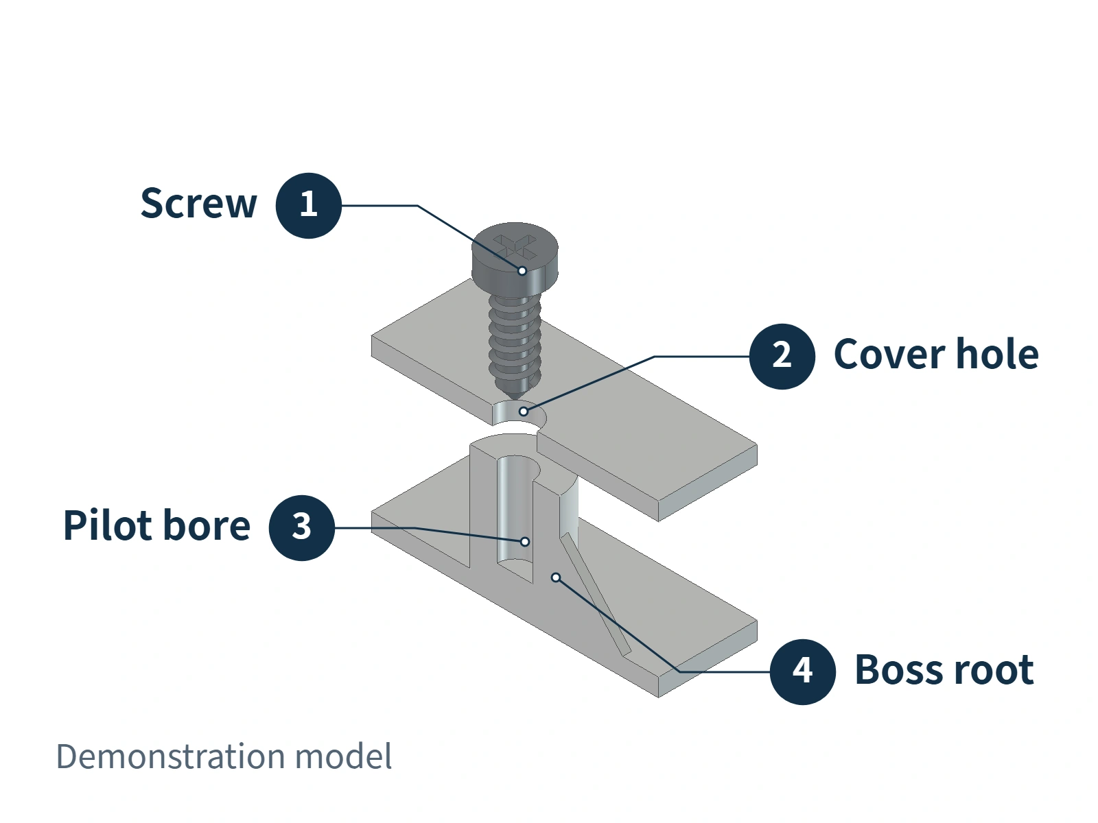
If you move the external screw hole, can the boss move with it? Is the new position already occupied by the circuit board, battery, or another component? If you shorten the boss to make the housing thinner, will the screw still have enough thread engagement? These relationships all need checking when the position changes.
Even when the position works, the pilot hole must suit the screw and the plastic material. An unsuitable fit between the hole and threads may fail to hold securely or place excessive force on the surrounding plastic during installation. Tightening torque also cannot be determined simply by whether the screw can be driven in.
Beyond the fit during installation, you also need to consider how plastic changes under sustained loading. Tightening the screw clamps the two parts together, but that clamping force may gradually decrease as the plastic remains under load. This involves “stress relaxation.” Even if the screw has not rotated loose, the parts may no longer be clamped as tightly as when first assembled. Feeling secure immediately after assembly is therefore not enough to show that the joint will remain suitable over time.
Moving just one visible screw can require changes to the boss, clearance around nearby components, and the joint itself. What needs to be preserved is a reliable fastening arrangement.
Which Appearance Changes May Keep the Existing Mechanical Design?
The three examples above share one feature: the change affects component positions, movement clearance, or connection conditions. The extent of the review depends on how much those conditions actually change.
| Proposed change | What needs checking? |
|---|---|
| Change only the color, keeping dimensions and internal fit unchanged | Whether the material and manufacturing conditions remain suitable; a color change alone does not establish that the entire mechanical design must be redone |
| Replace a smooth surface with a deeper texture | Whether the existing release conditions suit the new surface and whether the sidewall draft needs adjustment |
| Move a button or change housing dimensions or connection positions | Whether the original alignment, movement clearance, assembly fit, and fastening relationships still hold |
Texture is particularly easy to treat as surface decoration alone. Linh kiện Ép phun can reproduce texture from the mold surface. When the texture becomes deeper on sidewalls along the mold-release direction, the surface details may create more resistance during release and risk scuffing. The draft angles on those walls therefore need to be checked again. Keeping the overall dimensions unchanged does not necessarily eliminate manufacturing effects.
However, reviewing the mechanical design does not mean redesigning the entire product. Existing interfaces may be retained if they still work. If only one button is affected, you can start with its force transmission and stop features. A broader change to the layout and fastening may become necessary when a smaller housing no longer accommodates the internal components.
When discussing a product update, it helps to be more specific about “changing only the appearance.” Does it mean a new color or texture, a relocated button, or different dimensions? Which functions and components do you want to retain? Those details make it possible to judge what can stay and what actually needs redesigning.